Experimental CAD by Replacing Command Prompt Bar and Coordinates Input System with Voice and Gaze
Speculative CAD with Reflection from Emulation of AutoCAD R12 MS-DOS
ABSTRACT
This paper (essay) reports an experiment to replace command prompt bar and coordinates input system with voice and gaze as an alternative and speculative CAD system based on observation and analysis of emulation of an outdated CAD system, AutoCAD R12 MS-DOS. The emulation process provided materials and opportunities to compare and analyze recent AutoCAD systems with the outdated AutoCAD systems. This comparison allowed us to uncover the central ideas and concepts of AutoCAD that have been maintained since its initial release despite the numerous advanced features in nowadays’ AutoCAD. This emulation identifies the archetype of AutoCAD interface with command prompt bar and coordinates input system. From this emulation, this paper proposes a speculative CAD system replacing those two main elements of the interface archetype with voice and gaze input and discusses the potential and challenges of this experimental CAD system in design aspect.
1 AutoCAD R12
AutoCAD is a software application developed by Autodesk that enables computer-aided design (CAD) and drafting. The software is used to produce 2D and 3D drawings. AutoCAD software allows users to conceptualize ideas, produce designs and drawings to the required levels of technical accuracy, and even perform rapid design calculations and simulations; across a wide range of industries.
1.1 Backgrounds of AutoCAD
Introduced in late 1982, AutoCAD was one of the first CAD programs to run on a personal computer, especially an IBM PC. At that time, most CAD software ran on graphic terminals connected to mainframe or minicomputers. In the early days, it was treated as high-end software that ran on workstations, but it began to be used throughout design work when PCs became popular. Nowadays, the performance of home computers has improved overall, and they can also run on personal laptops.
John Walker, the main developer and founder of Autodesk, was a computer programmer. In 1974/1975, Walker wrote the ANIMAL software, which self-replicated on UNIVAC 1100 machines. It is considered one of the first computer viruses123. The first completed was AutoCAD from Autodesk, a software application for computer-aided design (CAD) and drafting. AutoCAD had begun life as InteractCAD, written by programmer Michael Riddle in a proprietary language. Walker and Riddle rewrote the program, and established a profit-sharing agreement for any product derived from InteractCAD. Walker subsequently paid Riddle US$10 million for all the rights. By mid-1986, the company had grown to 255 employees with annual sales of over $40 million. That year, Walker resigned as chairman and president of the company, continuing to work as a programmer. In 1989, Walker's book, The Autodesk File, was published. It describes his experiences at Autodesk, based around internal documents (particularly email) of the company4.
1.2 AutoCAD R12
AutoCAD R12 is the twelfth release of AutoCAD. Unlike the 8th release, which uses version numbers such as 1.0 and 2.1 to distinguish AutoCAD products, the 9th release begins using the release number directly with AutoCAD. By the year 2000, naming began by year like AutoCAD 2000. The release of the AutoCAD R12 suggests several meaningful points about the computing environment at the time.
There have been no new releases for the Apple Macintosh for more than a decade since this release, R12. In other words, R12 is the last release of AutoCAD for Apple Macintosh before AutoCAD 2002. This probably was related to what Mac users were reluctant at the time, and Apple had a crisis that caused sales to plummet. Also, two years after R12, Autodesk had announced AutoCAD R13 would be the last release for Unix, MS-DOS, and Windows 3.11. Autodesk focused on developing AutoCAD for Windows 95 after R13. Considering that the majority of applications release at the predecessor level and move to the next generation, R12 is at the summit of AutoCAD running on MS-DOS.
AutoCAD R12 is not very different from the current AutoCAD except for the variety of user interface. Even the overall composition of the interface is not much different from the current AutoCAD. At the bottom of the screen there is a command prompt bar which users can input their commands to generate shapes. At the top of the screen there is a menu bar allowing users to change and customize many properties and features of drafting system in the software. Between the prompt and menu bar, a modeling space is there with black solid background and white orthogonal guides. Of course, recent AutoCAD have more flexibility to their user interface applying ribbon-menu system, floating panels, pop-up instance information, etc. Despite the shift to a smoother and gentler interface, the fact that the overall structure does not change shows how the program supports design.
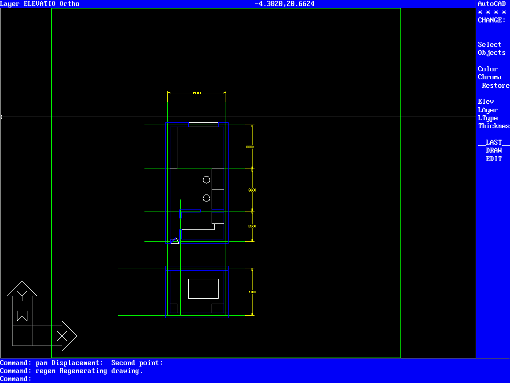
Figure 1: Screen of AutoCAD R12 MS-DOS Emulation
2 Emulation of AutoCAD R12
To illustrate a more vivid emulation process, this section describes it in a first-person narrative. Before starting emulation, this section introduces the AutoCAD that I have used in order to form a control group for AutoCAD R12.
2.1 2.1 AutoCAD 2006
It was ‘AutoCAD 2006’, the first AutoCAD that I had firstly used in architecture. In the first class of AutoCAD course in my 2nd year, I opened the AutoCAD executable file and learned six commands: line, erase, trim, copy, move, and zoom. After a while, I realized that these six commands were the most essential commands in AutoCAD for drawing drawings. The concept of commands, I used to play computer games with MS-DOS at the time, was quite shocked by the appearance of the command prompt bar. Due to the innovative advance of Windows, I had forgotten about the existence of command bar for about 10 years.
Few weeks after being familiar with these six commands, I drew a full set of drawings including plans, elevations, and sections through AutoCAD, it took almost 8 hours to finish them. The drawing principles in AutoCAD were same as in drawing board, such as extending lines on plans to elevations and sections. However, AutoCAD provides much more flexible controls which were enough to maximize someone’s work performance, such as copying and moving line objects. The impression of firstly plotting the drawings is unforgettable. Unique blade-like clarity, leading edge accuracy, lines that seem to be hard but contain the user's drafting identity, and information that appears to be mixed in a complex but subtle way and easily found…These all are called ‘Taste’ of AutoCAD among school of architecture students.

Figure 2: Interface of AutoCAD 2006
Since my AutoCAD has stopped in 2006. In terms of GUI, command, function, etc., I am a huge fan of AutoCAD Classic. For example, I am still using EPS format to export my drawings to other graphic software like InDesign, Photoshop, or Illustrator. At that time, 2006, as pdf was not easily recognized as vector graphics by other graphics programs, users plot their drawings into the EPS format compressed with post-scripts-level2 in dwg files to convert dwg and make them compatible with other graphic software. I'm currently using AutoCAD 2019 LT, but I always find myself spending five hours trying to restore the Classic UI as default. This shows not only the importance of the feelings of comfort that come with familiar software interfaces, recognition that AutoCAD is treated as the same program despite various updates and version changes.
To me, AutoCAD R12 satisfied my expectations and fears together. I, who are feeling the current development of AutoCAD cumbersome and handling current AutoCAD as AutoCAD 2006 despite of using new features of current one, was curious about what AutoCAD R12 has, and what was AutoCAD's first intention and essence. With this expectation, I was afraid and anxious of using the new program.
2.2 Command-based Drafting
Just after opening the AutoCAD R12 in MS-DOS, firstly, I tried to find command bar where all drawings start in AutoCAD. Fortunately, like recent AutoCAD, R12 has a command bar with its own style which is compatible with MS-DOS. Of course, this command bar is fixed and rigid, compared to recent AutoCAD one which size and position can be modified due to ‘Floating Panel’ concept in user interface (UI). As I have yet to send the Classic UI (the first taskbar and button-based interface introduced since 2002) and I am stranger to the Ribbon UI, the presence of the fixed command bar in R12 provides a great stability in usage of unfamiliar software.
After typing ‘la’ which represents layer options, I hit space bar. Surprisingly, both trial commands worked. R12 recognized ‘la’ as a command for controlling layers and space bar a command for entering and confirming commands. Unlike recent version of AutoCAD, layer option panel did not pop-up. Instead, it returns a dialogue in command bar with several options of layer features: “Layer ?/Make/Set/New/ON/ OFF/Ltype/Freeze/Thaw/Lock/Unlock”. I was able to create a new layer by typing ‘New’ and name of a new layer. For a more visual analysis of layer features, I clicked the Layer function in the Settings menu in the Task Bar at the top of the screen. Due to the difference in operating systems (OS), the MS-DOS style panel, which is graphically different from recent layer panels, popped up providing similar features to the recent one. This panel provides features to create new layers and changes names, colors, line types, and line thickness of them. This panel employs the Color Palette system that AutoCAD currently uses. The Color Palette system is a kind of color alias system that pre-stores RGB values of commonly used colors and easily distinguishable colors, and assigns them to specific colors such as Color 25. The official AutoCAD website shows that this color palette system was introduced in R12.
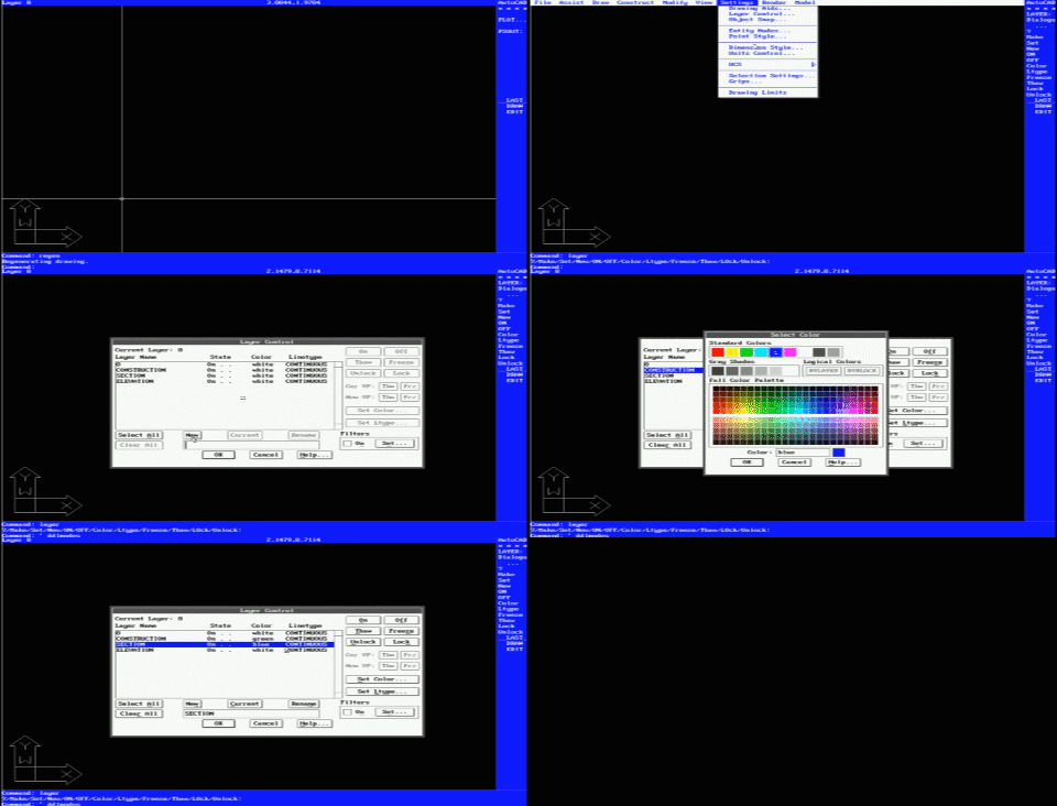
Figure 3: Layer Setting Dialogue and Panel with Color Palette
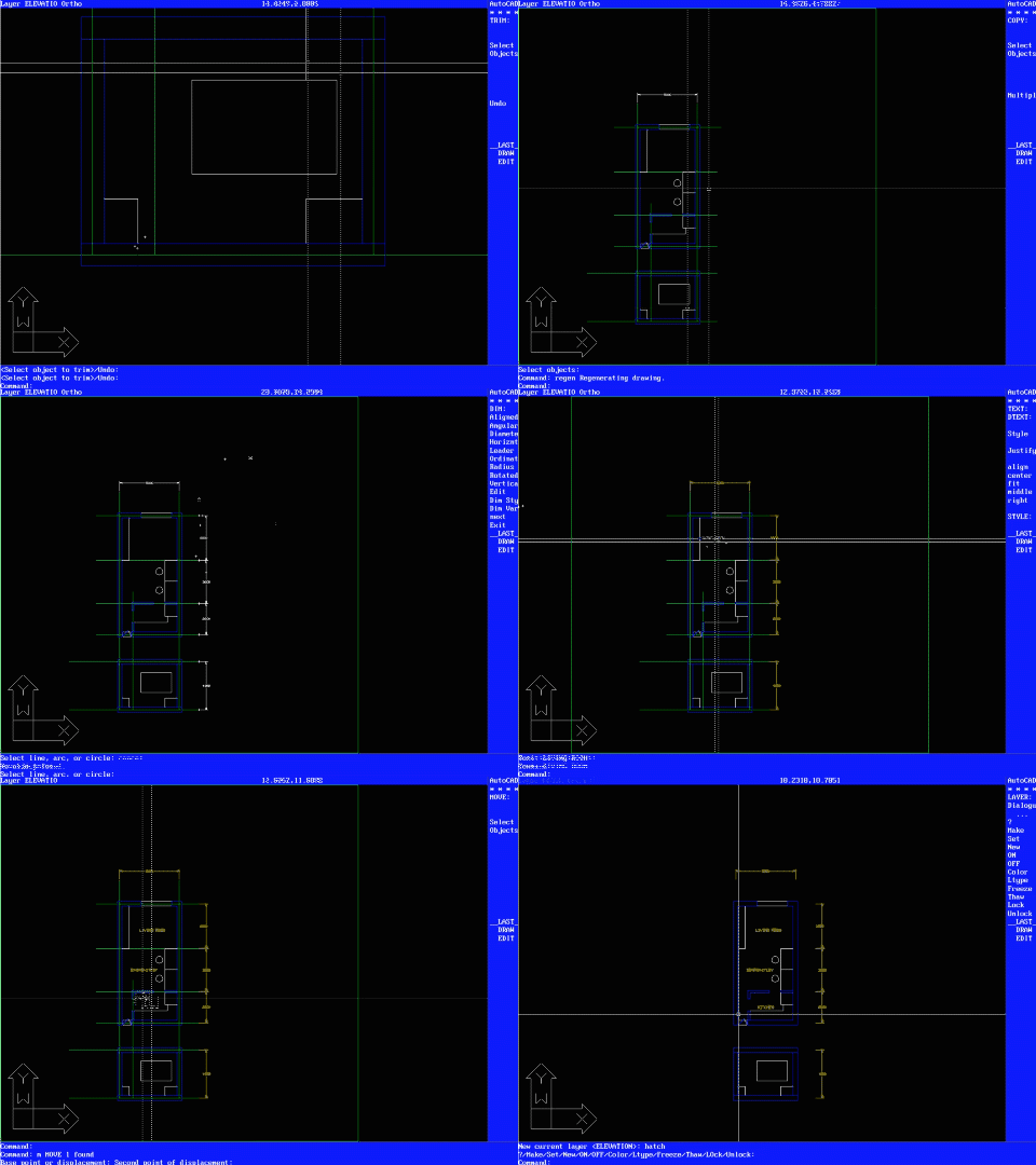
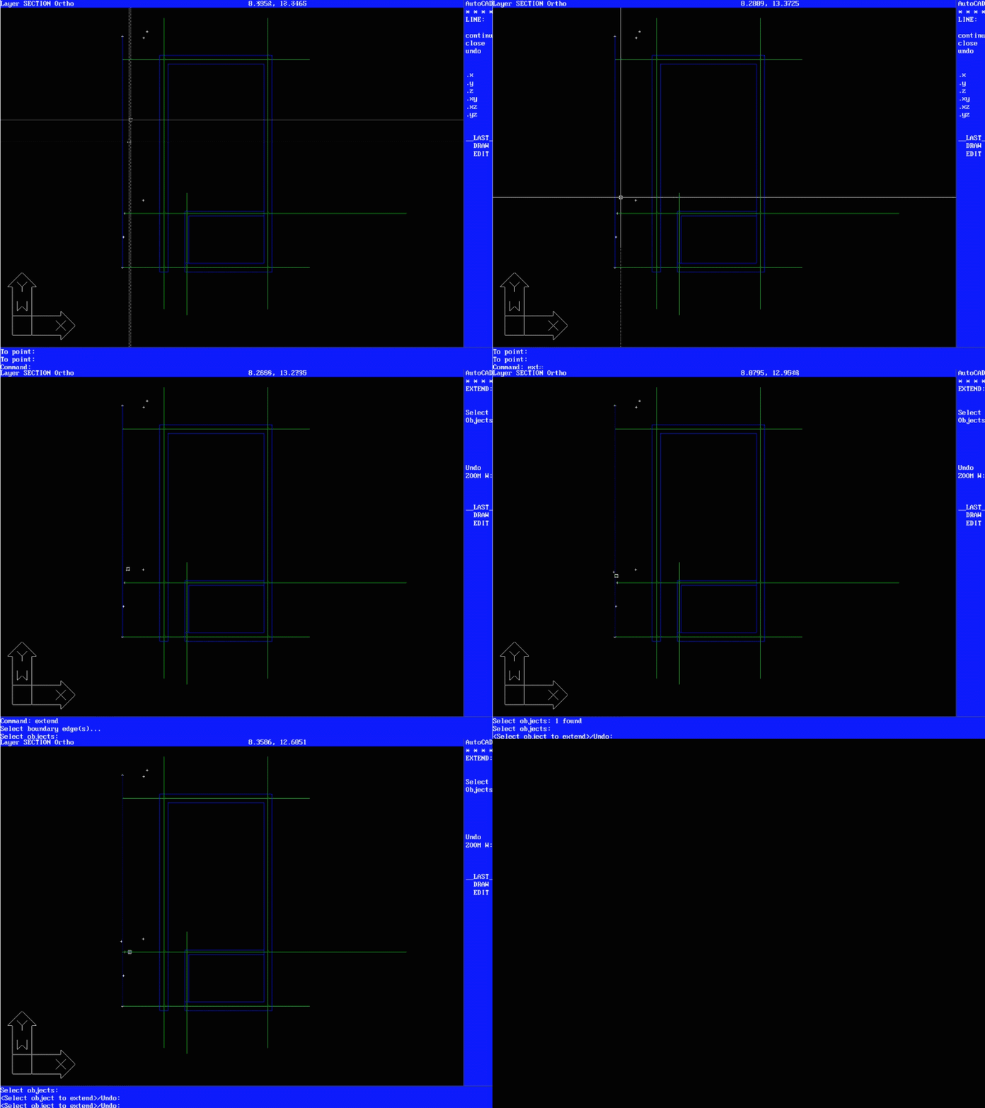
After creating layers for construction lines, section lines, and elevation lines, I set the construction lines layer as current layer. Then I started draw construction lines by using Line (ln) and Trim (tr) commands. The command system in R12 requires entering a command that performs a specific action and return a dialog specifies options or reference values for the command. This system is quite similar command system to recent AutoCAD. The main difference between these two command systems is the rigidity of input information. R12's command system tends to be more rigid than current command systems. For instance, in Trim command, the object to cut must be selected before the object to be cut. In Extend command, the object to be used as the extension reference must be firstly selected. Today's AutoCAD has a command system that works more intuitively by determining the position of the mouse, less sensitive to the order of selection. For example, ‘Extend’ command requires the selection order of lines by distinguishing boundary object and the object to be extended.

Figure 4: Object snap setting panel
The drafting aids also work similar to recent AutoCAD. Like F7 and F8 key enabling or disabling Grid snaps and orthogonal drawings, there are shortcuts working same as recent AutoCAD. Otherwise, like F3 enabling object snap, there are shortcuts not working same as recent AutoCAD. It seems that F3 shortcut was not assigned yet in R12. However, not assigning shortcut does not mean absence of this function. Object snap can be set through menu in task bar. The snap function selects the point nearest the mouse pointer, depending on the type of point. Currently, AutoCAD displays snapped objects with unique orange markers and constrains mouse movements to help users select the desired object snap. R12's snap does not yet provide such an advanced snap interface. R12 recognizes points of different types on the same principle as the recent AutoCAD one, but does not show them graphically. The user may actually be confused because they are visually notified whether or not their mouse pointer is constrained from the snap point.
Current settings of activation of drafting aids are displayed in the command window and status bar at the top of the screen. This is different from the way that recent AutoCAD shows them through the buttons at the bottom of the screen. Still, AutoCAD provides users with real-time information using text and commands rather using buttons or panels.
I used Offset and Fillet commands to draw wall section lines in plans from construction lines. In fact, while typing these commands, I was already prepared myself to draw the outline of the wall using copy, extend, and trim commands with the doubt that it would exist. To my surprise, the commands worked. It was like trying to fix an old, rusty piece of clock with a modern, sophisticated tool that felt very well. As I redrawn the lines in R12, I gradually adapted to the old drafting system R12 had, and for about an hour I was able to finish drawing lines in plans. Because R12 has the function of annotation and dimension, I typed “text” to write simple text on my drawing. Those functions work very similar to recent AutoCAD.
Surprisingly, AutoCAD R12 MS-DOS version supports simple 3D geometries. Unfortunately, as the emulated AutoCAD R12 in this virtual environment does not have specific codes to operate 3D function, I cannot use the function. However, the presence of 3-D geometries in ACAD R12 shows that the Autodesk has long been invested in developing 3-D modeling technologies. One of the reasons why AutoCAD cannot give up the function to support 3D geometry is demands from CAM industries. Although the 3D function in AutoCAD R12 seems not enough to be used as design tool, it might be useful to review three dimensional models and convert the model into 2D drawings.
In terms of zoom and mouse control, when users emulate R12, they need to know and realize the difference between current mouse technology and 20 years ago one. First, there was no ‘wheel’ in mouse. Usually, in recent AutoCAD supports wheel button in mouse to control zoom in and out. Due to the absence of the wheel button in early of 1990s, zooming by wheel does not work in R12. Given that the mouse was a mechanical mouse with a gray ball at the time, we can't assume that this CAD supports Mouse Pointer Acceleration. Therefore, I disabled Mouse Pointer Acceleration and decrease the sensitivity to properly control the mouse in AutoCAD R12.
Furthermore, zoom function does not have margins. If you are familiar with recent AutoCAD in practice, you know what habitually pressing the zoom extents is. It is to type ‘Z’ (alias of zoom) and ‘E’ (alias of extents) continuously after a single job without any purpose in order to see the overall frame and status of drawings after editing or adding specific parts of your digital drawings. When this command is executed, the screen shows the entire drawing with a reasonable margin. However, in R12, it does not give you any margin. It will move the screen accurately according to the minimum and maximum x-y values of the objects. One of the most frustrating factors is the lack of free space for the mouse to move. By adding Hatch like recent AutoCAD, I finished my drawings. I realized that if I use this version of AutoCAD more and more, I can draw more detailed drawings overcoming few frustrating differences between recent AutoCAD and this version.

Figure 5: Plan and Section created through AutoCAD R12 (left) and 3D view (right)
3 Drafting or Design Tool
From the emulation above, I realized two things: AutoCAD's interface consistency and direction. The fact that users who have never used an older version of AutoCAD can create a drawing without the huge inconvenience and only with one-hour exercise shows that the principle of operation or interface of AutoCAD has a certain consistency. This consistency can simply be interpreted as a result of AutoCAD's conservatism, but perhaps this is the orientation that AutoCAD has had since its inception.
3.1 Interface Archetype of AutoCAD
AutoCAD was originally developed as a tool replacing a traditional architectural designer’s desk with pencils, yellow tracing paper, and T-square, as their name of company indicated (Auto + Desk). Comparing and contrasting the typical architect's drawing board configuration with the AutoCAD R12 user interface makes AutoCAD's role more apparent. At the bottom of the drawing there is a narrow and long cradle, where you can place a triangle, protractor, compass, lettering ruler, eraser and ink. In other words, this is where the drawing begins, giving users the option of choosing a tool based on which geometry they want to draw. In AutoCAD, the command prompt bar, which can take drawing commands from users, is also located at the bottom of the screen or at the bottom of the drawing space. In AutoCAD, the T-square on the drawing board has been replaced by the vertical guidelines of the mouse, and the tray on the right side of the board, which contains various auxiliary drafting tools, such as different thickness and colors of Rotring pens, has been replaced by a contextual menu area that provides options and properties. Zoom magnifier is changed as a command system providing variety version of zoom-in and out to users. A typical menu bar, like all other application programs in computer, is not on the drawing board. This menu bar presented a software view of a given interface or environment for solving a problem.
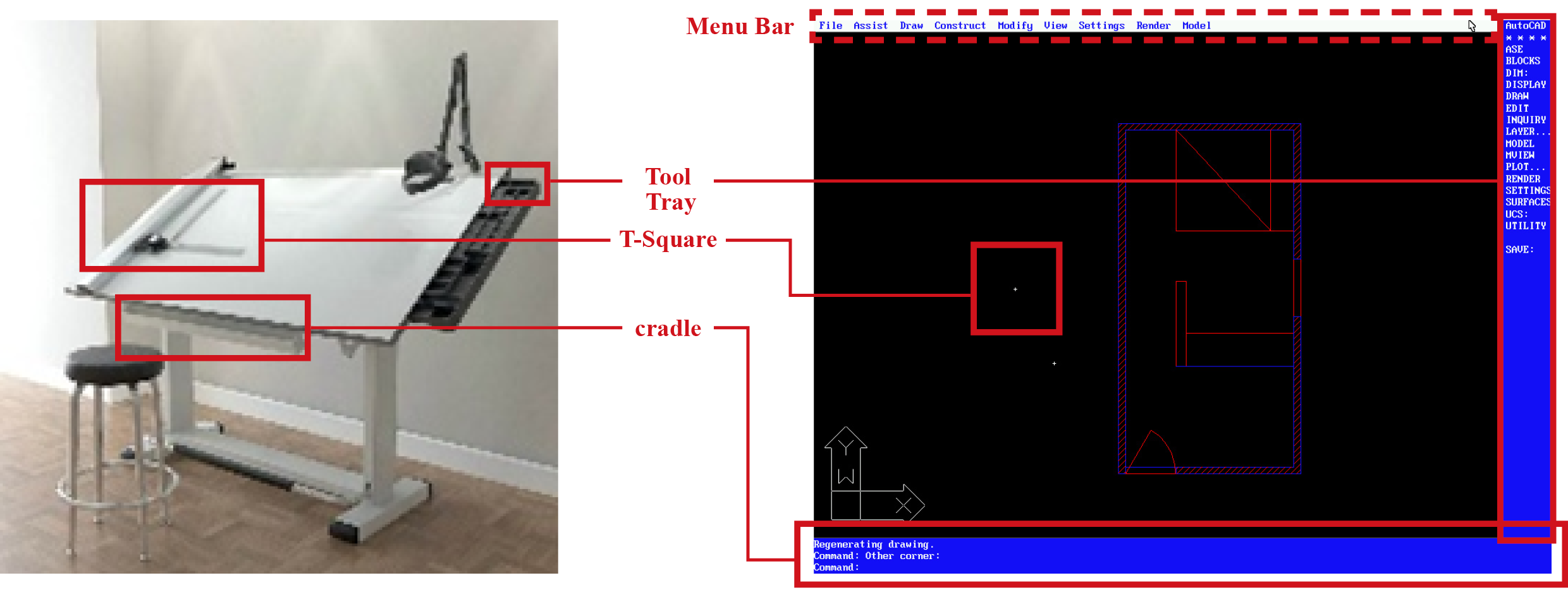
Figure 6: Interface Comparison Between Drawing Board and AutoCAD R12
AutoCAD's interface with command prompt bar, coordinates spaces, menu bar, and tool tray, which began by digitizing drafting boards, constitutes a classic or archetype of CAD interface. Most of nowadays CAD systems, such as FreeCAD, Rhinoceros, CATIA, CADRA, Corel CAD, LibreCAD, ZWCAD, etc., follow the configuration of this interface archetype, although there are minor differences. But we can see that BIM programs like Revit do not follow this configuration. The command prompt bar is not required for BIM programs. This difference can be a small one, but it shows how the design object is perceived. Displaying objects in coordinate space based on commands and editing them using various tooltips and functions is inherited from the drawing board. On the other hand, in BIM, where the system of a building is treated as the hierarchy and system that computers have, the overall composition rules and orders are more important than editing these objects. Therefore, the role of the command prompt bar to enter each command is considered insignificant or optional.
3.2 AutoCAD's Position in Design
AutoCAD, which intention was leading to the demise of the T-square, has been quite successful to achieve their main purpose in that we can easier find the screen of AutoCAD than drawing boards in most architectural offices nowadays. However, besides increasing productivity through automation, it is true that AutoCAD has not been very effective in architectural design. Although it proposed a standardized drawing format that facilitates communication between different disciplines of architecture and opens the door to unifying information, it cannot be said that the use of AutoCAD has led to critically changes in architectural design.
Although AutoCAD almost perfectly digitalized many parts of drafting, we can rarely this drafting tool is used as design tool rather than drafting tool. AutoCAD was originally developed as a tool replacing a traditional drafting man’s desk with pencils, yellow tracing paper, and T-square, as their name of company indicated. It was successful to remove drawing board from architect’s desk but not successful to remove tracing paper and pencils. In architectural practice, we can see many architects are still using tracing paper and sketches with AutoCAD.
The most critical question about the future of AutoCAD is “Do we still need drafting tools?” Nowadays, many design tools support drafting functions, such as Rhinoceros or Revit. From Rhinoceros 5.0-6.0, drafting features such as annotation and measuring dimensions were innovatively strengthened. More boldly, Revit no longer sees drafting as a work, but as one form of results from the building systems. On the contrary, AutoCAD, the most widespread drafting tool, strengthens their design features. From AutoCAD 2013, it started to support ‘parametric’ functions to draw objects with parametric constraints, and NURBS curves. In short, one of the import trends of current CAD is that design tools are strengthen their features of drafting and drafting tools are strengthen their features of design.
Emulation of AutoCAD R12 shows the essence feature of AutoCAD and the importance of interface in drafting tool. Instead of adding more and more rarely used features and specified features, AutoCAD should have focused on developing and improving their interface into more intuitive one. It is a time to break the illusion that AutoCAD can be one powerful CAD software in design industry integrating drafting and designing features. This integration continues to make AutoCAD heavier and eventually many users go away from AutoCAD.
4 Speculative CAD
From emulation, I realize two elements that are most essential in AutoCAD interface: command prompt bar and coordinates input. Both of these elements do not actually support intuitive design. A command is an interaction that takes place in three steps. The user must recognize the object currently displayed on the screen, imagine any geometrical changes, and then specify the appropriate command or sequence of commands to implement it. A coordinate input system is also an element in which drawings are created only after several steps. It is a system that requires users to imagine the shape of an object and then calculate and input its vertices’ coordinates considering the length and angle.
This speculative CAD experiment was motivated at this prolonged immediacy. By proposing alternative systems for command bar and coordinates input, this section implements CAD to further increase the immediacy of existing CAD systems, and analyze their potentials and challenges.

Figure 7: VOIZE CAD, a CAD prototype with voice and gaze control
4.1 From Command Prompt Bar to Voice Recognition
In order to replace command prompt bar from CAD system, I employed voice recognition to control CAD commands. I used Google’ voice recognition model. Instead of typing and inputting a full-name, shortcut, alias of commands, users can say a command and detail information. For example, in AutoCAD, when users want to draw a rectangle, they need to type ‘rec’, the alias of ‘Rectangle’ command, and input other details, such as the coordinates of the first and another corner of the rectangle. On the other hand, in CAD with voice command system, users need to say ‘rectangle’ and coordinates details like “three dash two and five dash minus one”.

Figure 8: Drawing Rectangles with Voice Command System in CAD
However, even if the CAD system can recognize and respond to the user's voice commands, ultimately the user must specify a modeling space consisting of coordinates. The problem arises here. Since the coordinate system consists of symbols and norms, it is more inefficient to convert them to voice or sentences. For example, when users specify a point (3,2), they should say a point as “three comma (or dash) two”. Simply comparing the length of the representation, you can see that converting a coordinate of a vertices to a sentence increases the amount of information. To overcome this inefficiency, I eventually had to introduce another system that could specify coordinates.
4.2 Gaze: Seeing is Drawing?
In order to compensate the bottleneck of voice system in CAD described above, I employed gaze tracking system. An attention point from gaze tracking plays a role of mouse pointer, and blinking patterns work like a variety of mouse clicks. For example, half blinking is dragging mode, and double blinking is confirming. The relationship between voice and gaze system is obvious: voice system will take charge of command prompt bar for inputting commands and gaze system will take charge of command details such as specifying coordinates.

Figure 9: sPlan and Section created through AutoCAD R12 (left) and 3D view (right)
Gaze tracking, unlike voice input, allows users to select coordinates more intuitive and faster. The relationship between voice and gaze system is obvious: voice system will take charge of command prompt bar for inputting commands and gaze system will take charge of command details such as specifying coordinates. It shows higher immediacy than existing CAD system. Existing CAD systems had to be typed at least. The gaze tracking system, however, can literally specify coordinates in the blink of an eye without this typing.
5 Conclusion
I emulated an older version of AutoCAD and compared it to the recent AutoCAD environment to find out what orientation AutoCAD had. It revealed the persistence of the interface even in the development of various updates and functions, and revealed the archetype of the interface of the CAD system. Asking about this archetype, I experimented with a new CAD system to replace the command prompt bar and coordinate input system in a more intuitive way.
Speculative CAD successfully achieved the goal of replacing command prompt bar with voice and coordinates input with gaze tracking. However, the prototype, which was designed to increase immediacy, seemed more difficult to allow for a more intuitive design than expected earlier in the project. Apart from the problems of technical shortage and immaturity of implementation, this process confirms a very obvious proposition that seeing is not drawing. The eye has priority as a sensor to receive information. Directly and immediately linking viewing information to the act of drawing doesn't work very well in terms of design. In other words, another step between viewing and drawing should be like a buffer.
Simply using voice and gaze with the ability to paint doesn't seem reasonable. Beyond drafting through one user's display, it is expected that these technologies can play a different role in collaborative systems in virtual worlds. If one user looks at the object of drafting or design through voice and gaze in the virtual space and simulates the editing, it can be expected to be used in the virtual drafting space where other users can share their intentions. Voices and gazes can play an important role, not as tools for directly controlling or drawing objects, but as tools that can inform a user's design or drafting intent.
Another value found in this prototype is assistive technology. Away from the frame of software development, assuming CAD's users have access to the mouse and keyboard, the prototype showed the potentials of providing opportunities of use of CAD systems for drafting and designing to people with different abilities.
REFERENCES
Parikka, Jussi (2007). Digital Contagions: A Media Archaeology of Computer Viruses. Peter Lang. pp. 41, 239–40. ISBN 9780820488370.
Stern, Zack (May 2008). "White Paper: The Evolution of Viruses". Maximum PC. Retrieved March 20, 2012.
Walker, John (August 21, 1996). "The Animal Episode". Fourmilab. Retrieved March 20, 2012
https://en.wikipedia.org/wiki/John_Walker_(programmer)
